Reed switch sensors pilot loads — Series 50 relays switch them. Solid state AC switching from 24–240V with no moving parts, no arcing, and no audible clicking. Designed expressly for OEM integration with ERECTA SWITCH sensor systems.
Why you need a relay with your ERECTA SWITCH sensor: Reed switch sensors deliver reliable, low-power contact closure — but they cannot directly switch pump motors, solenoids, or high-current loads. Series 50 relays bridge that gap. The sensor pilots the relay; the relay switches the load. The result is a complete, solid-state control circuit with no mechanical contacts to wear out.
Two relay architectures — non-latching for simple on/off, latching for wide-differential level control.
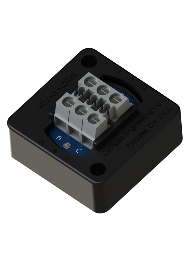
Solid state AC switching relay that turns ON when the sensor switch closes and turns OFF immediately when the switch opens. The simplest relay configuration for direct on/off load control. Available in 1-pack and 5-pack. Eurostyle screw terminals. Built-in heat sink sufficient to 0.75A continuous — attach to supplemental heat sink above that threshold.
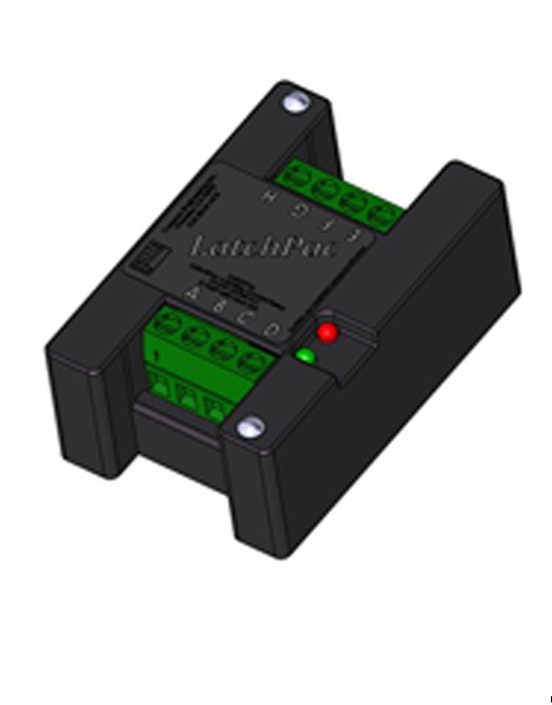
Solid state latching relay for wide-differential level control. Combines two ERECTA SWITCH sensors to create precise start/stop setpoints — one switch starts the latch energizing the load, the other stops it. Eliminates short-cycling and sensor chatter in pump and valve control applications. 10A continuous load capacity.
It is a solid state AC switching relay for OEM equipment. A reed or float sensor gives a reliable, low-power contact closure but cannot directly drive a pump motor, solenoid or other high-current load. The Series 50 relay bridges that gap: the sensor pilots the relay, and the relay switches the load — letting a sensor handle a bigger job than it could by itself.
Any dry contact or passive SPST sensor will pilot it — reed switches, float switches, bimetallic temperature switches, flow switches, magnetic contacts, thermostats and pressure switches. That makes it useful well beyond liquid level: thermal shutdown interlocks, HVAC damper and blower control, and light-duty feeders or mixers driven from a simple contact closure.
Series 50 relays switch line-voltage AC loads, and the exact voltage range, continuous load rating, maximum surge and minimum load are listed in the specification table on this page — they differ between models, so read the table for the one you are specifying rather than assuming. Note there is a MINIMUM load as well as a maximum: below it the relay may not switch cleanly.
Eurostyle® screw terminals take three pairs: line voltage, the load device, and the sensor. The load connects to terminals A and F, line voltage to B and E, and the sensor to C and D. Control is simply completing and interrupting the sensor circuit — the load stays on for exactly as long as that circuit is complete. Observe polarity conventions for your line and load circuits and fuse both to the applicable equipment codes.
It depends on the current you are switching, and the threshold is on the specification table on this page. The relay dissipates heat only while the load is on. Below the stated threshold the built-in heat sink is sufficient; above it, the relay must be attached to a supplemental heat sink or any cool metal surface of adequate area to keep it from overheating.
It has no moving parts, so it is silent, cannot suffer contact wear, and does not arc. That matters in OEM equipment expected to cycle for years without service, and in enclosures where arcing contacts are undesirable. ⚠ Note it is a solid state device: it passes a small leakage current through the load terminal even when off, which the specification table quantifies — check that your load tolerates it.